# Process Template Diagram and Guidelines
The **Process Template Diagram** is the core workspace in **Process Designer** where business processes are visually modeled and implemented.\
It uses a simple **drag‑and‑drop graphical interface** based on **BPMN (Business Process Model and Notation)** to represent and configure business activities.
By using BPMN standards, the Process Template Diagram enables:
* Clear interpretation of business logic
* Effective collaboration between business and technical users
* Easier maintenance and enhancement of process definitions
***
### Process Template Diagram Layout
The Process Template Diagram is divided into **three main panels**, as shown below.
#### Panel Overview
1. **Node Task Panel**
2. **Diagram Panel**
3. **Action Panel**
Each panel is described in detail below.
***
\##📦 Node Task Panel
The **Node Task Panel** contains all available **process activity nodes** (BPMN elements).\
Each node type represents a specific business purpose.
Examples:
* **Human Task** – Used for tasks assigned to a Work Party (users or roles)
* **Database Task** – Used for database operations
* **Gateway** – Used for decision logic
* **Start / End Events** – Used to define process boundaries
For detailed descriptions of each node type, refer to the\
**Activity Nodes** section.
***
### Diagram Panel
The **Diagram Panel** is the central canvas where the business process is designed.
Capabilities include:
* Dragging nodes from the Node Task Panel
* Connecting nodes to form process flow
* Right‑clicking a node to:
* Open configuration
* Add boundary events
* Delete nodes
This panel visually represents the complete execution logic of the process.
***
### Action Panel
The **Action Panel** provides editing and navigation tools for the diagram.
#### Action Icons and Functions
| Action | Description |
| -------- | ---------------------------------- |
| Undo | Undo the last action |
| Redo | Restore a previously undone action |
| Delete | Delete the selected object |
| Cut | Cut the selected object |
| Copy | Copy the selected object |
| Paste | Paste the copied or cut object |
| Zoom In | Increase diagram size |
| Zoom Out | Decrease diagram size |
These controls help manage large or complex process designs efficiently.
***
### Process Template Diagram Creation Guidelines
A Process Template Diagram is created by dragging nodes onto the diagram panel and configuring them step by step.
Below is a **sample guideline** for creating a process flow.
***
#### Step 1: Add Horizontal Lane
Begin by dragging a **Horizontal Lane** into the diagram panel.
> ℹ️ **Note**\
> For more details, refer to **Pool / Lane** section.
***
#### Step 2: Add Core Process Nodes
Drag the necessary nodes to the diagram panel:
* **Start Event**
* **End Event**
* **Exclusive Gateway**
* **Human Task**
* **Database Task**
***
#### Step 3: Connect Nodes
Create process flow by connecting nodes:
* Hover over a node
* Select one of the available connector ports
* Drag the connector to the target node
***
#### Step 4: Rename Nodes and Configure Gateway Paths
Double‑click nodes to rename them:
* Database Tasks →
* *Get User Information from DB*
* *Save User Status to DB*
* Human Task → *Approve Inbox*
* Gateway → *Check Approve*
Rename outgoing gateway paths:
* Approve
* Reject
Configure gateway conditions via the **Gateway → Condition** tab.
***
#### Step 5: Configure Business Object Mapping
1. Double‑click a node and open the **Business Object** tab
2. Enable **Input** and **Output**
3. Click **Open Mapping Parameter**
Map parameters between:
* Process Input
* Activity Parameters
* Process Output
Click **Done** to save mappings.
***
#### Step 6: Configure Database Task
Open **Database Parameters** tab and define:
* Connection Type: JNDI
* JNDI Name: `jdbc/application`
* Command Type: SELECT
* SQL Query
```
select leave_id, type, status, decision
from erp_oneweb.hr_leave
```
***
#### Step 7: Configure Assignment Policy
For the Human Task:
* Open **Assignment Policy**
* Setting: Pull
* Work Party: Approver
***
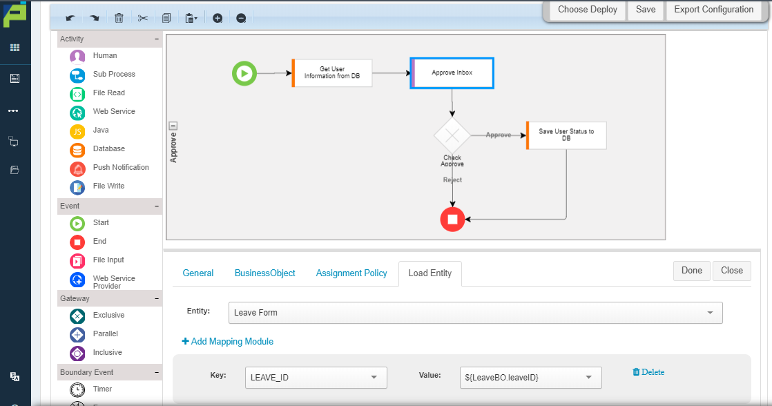
#### Step 8: Configure Load Entity for UI Integration
Open **Load Entity** tab:
* Entity: Leave Form
* Key: LEAVE\_ID
* Value: `${LeaveBO.leaveID}`
***
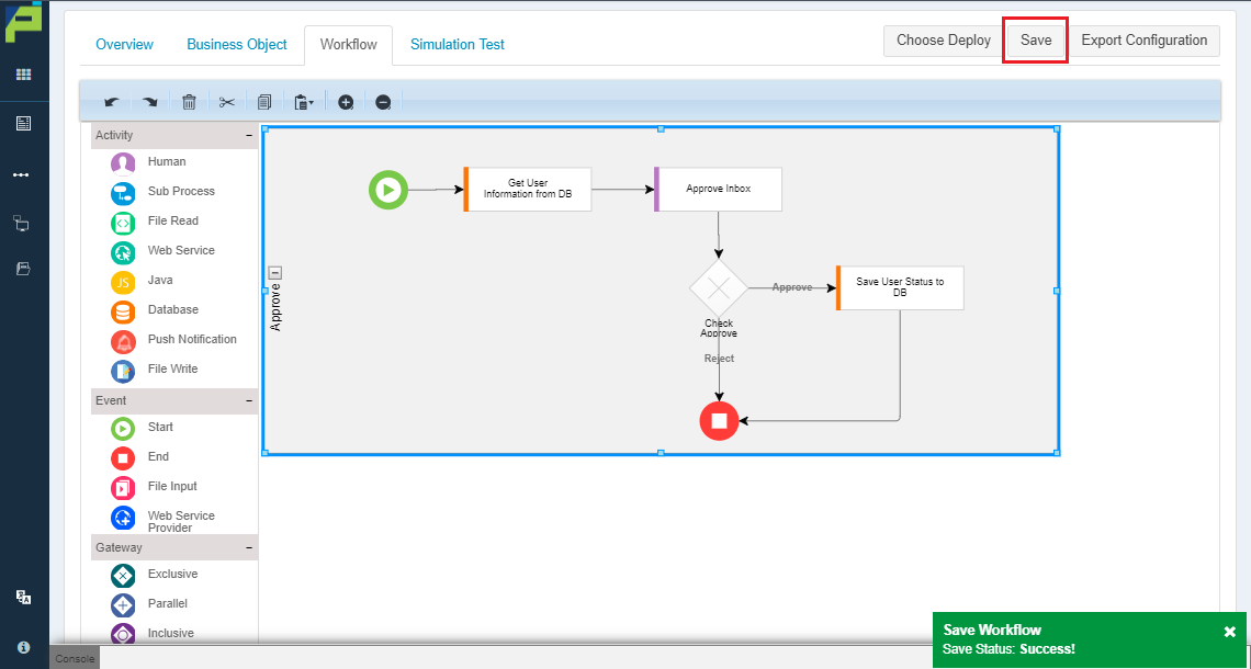
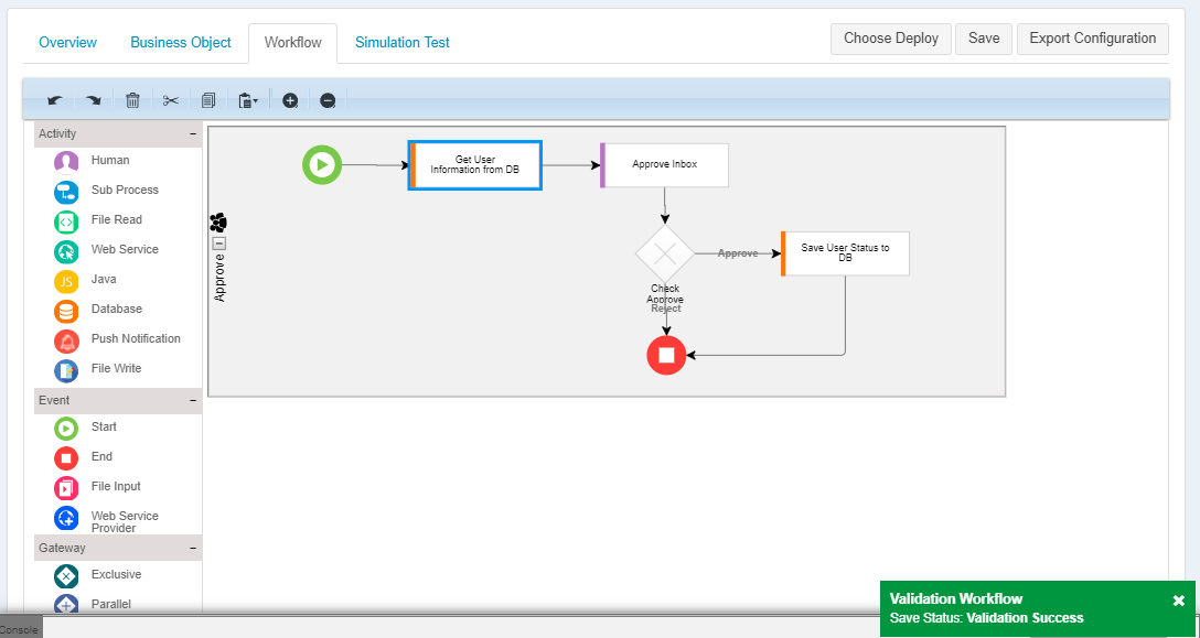
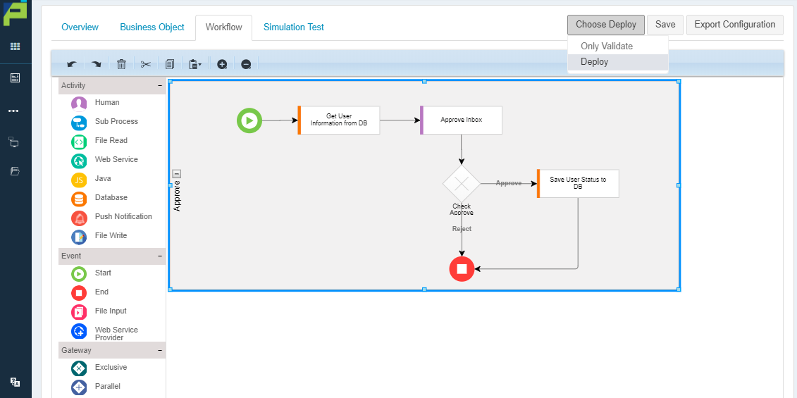
#### Step 9: Save, Validate, and Deploy
Once all nodes are configured:
* **Save** the process
* **Validate** the diagram
* **Deploy** to runtime environment
***
### Summary
The **Process Template Diagram** is the foundation of workflow execution in ONEWEB.
Key takeaways:
* BPMN‑based visual modeling
* Drag‑and‑drop process creation
* Clear separation of responsibilities
* Strong support for business‑technical collaboration
* Full lifecycle: design → validate → deploy
Mastering the Process Template Diagram enables users to build **scalable, maintainable, and executable business workflows** in ONEWEB.
---
# Agent Instructions: Querying This Documentation
If you need additional information that is not directly available in this page, you can query the documentation dynamically by asking a question.
Perform an HTTP GET request on the current page URL with the `ask` query parameter:
```
GET https://docs.onewebstack.com/designer-reference/process-designer/create-new-process/process-template-diagram-and-guidelines.md?ask=
```
The question should be specific, self-contained, and written in natural language.
The response will contain a direct answer to the question and relevant excerpts and sources from the documentation.
Use this mechanism when the answer is not explicitly present in the current page, you need clarification or additional context, or you want to retrieve related documentation sections.